Automatic Disconnection of Supply and Earth Fault Loop Impedance
This blog contains the following:
1. Introduction to Automatic Disconnection of Supply
2. Calculation for ADS using MCB
3. Calculation of Permissible Earth Fault Loop impedance
4. Calculation of Earth fault Loop Impedance
5. Problems associated with manual calculations
6. Earth Fault Loop Impedance calculation using ElectricalOM NEC-IN
1. Introduction
The most common protective measure against electric shock is Automatic Disconnection of Supply, abbreviated as “ADS” (IS 732 4.2.11).
ADS is a combination of the following protective provisions:
1. Basic Protection: provided by a combination of basic insulation, protective barriers or enclosures between hazardous-live-part and exposed-conductive parts; and
2. Fault Protection: provided by protective equipotential bonding and automatic disconnection in case of a fault of negligible impedance between a line conductor and an exposed-conductive-part or a protective conductor.
Meaning: If fault protection is to be achieved in an installation, the supply shall be disconnected within the prescribed time. This time will vary depending on the following parameters:
1.Type of circuit (distribution circuit or final circuits)
2.Nominal line to earth voltage
3.Type of system earthing (TN or TT)
4.Type of current (a.c or d.c)
The specified times for final circuits are provided in the below figure (IS 732 Table 1):
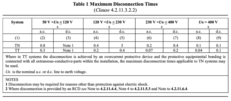
For a circuit to be disconnected in the above-prescribed time, coordination between the protective device and circuit is required.
The operating time of an overcurrent protective device (such as MCBs, MCCBs and ACBs) is defined by current-time graphs provided by their manufacturers or product standards.
2. Example Calculation using MCB for ADS:
For MCBs, Table 2 of IS/IEC 60898-1 defines the operating current for instantaneous tripping in multiples of the nominal current (In) for different type of overcurrent characteristics i.e. B, C or D.

As an example:
B16 MCBs conforming to IS/IEC 60898–1 will have the following current-time operating characteristics:
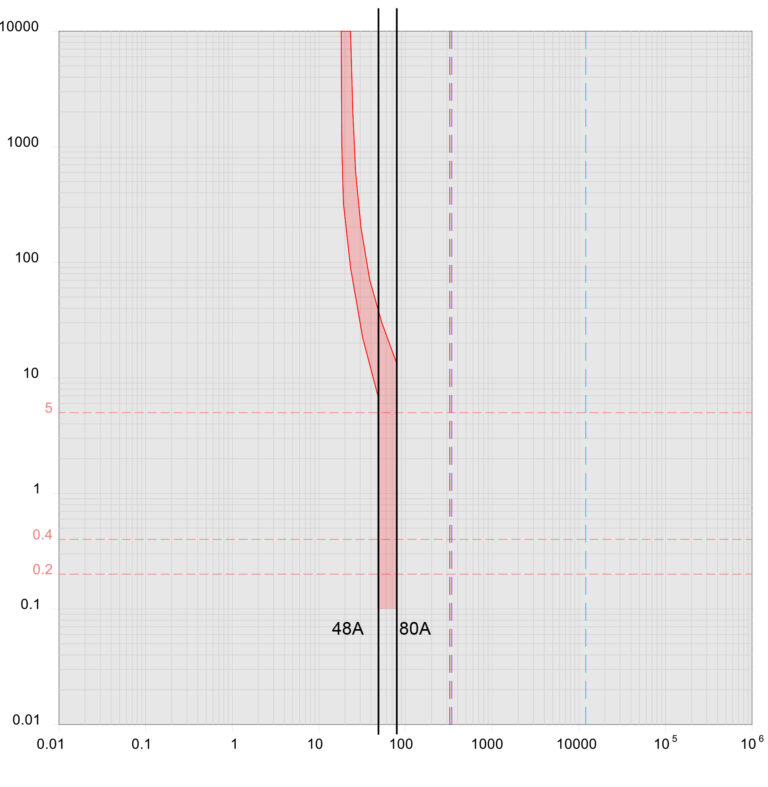
As observed from the current-time characteristics of the B16, the graph shows a range for instantaneous operation between 48A (A) and 80A (A).
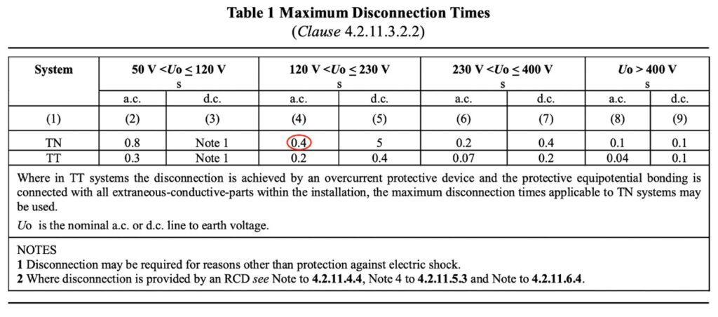
If we assume this B16 MCB protects a final circuit as part of a TN system, with Uo=230V, the maximum disconnection time is 0.4s (IS 732 Table 1):
In order to ensure the operation of the protective device in the required time, a fault current of 80A is required. The value of 80A corresponds to 5 In, which is the upper end of the range. When considering minimum current required for the operation of an overcurrent device with respect to automatic disconnection of supply, the minimum current is taken as the upper end of the device’s disconnection current.
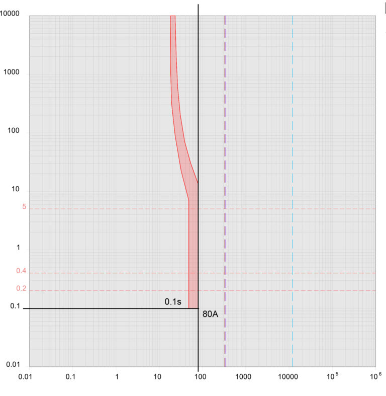
From the above information, it can be ascertained that in order for a B16 MCB to provide against electric shock, a minimum fault current of 80A must flow in the event of a fault of negligible impedance between the line conductor and an exposed-conductive part or protective conductor.
3. Calculation of Permissible Earth Fault Loop impedance
The Earth Fault Loop Impedance at the extremity of a circuit needs to be limited to a value (Zs) such that (Cl. 4.2.11.4.4, IS 732:2019):

where
Zs = the impedance in ohms (Ω) of the fault loop comprising
the source,
the line conductor up to the point of the fault, and
the protective conductor between the point of the fault and the source.
Ia = the current in amperes (A) causing the automatic operation of the disconnecting device within the time specified in Cl. 4.2.11.3.2.2 or Cl. 4.2.11.3.2.3 of IS 732:2019.
Uo = the nominal a.c. or d.c. line to earth voltage in volts (V).
For the given case from the above example calculation,
Ia is known to be 80A and Uo =230V,
Hence:
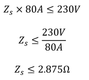
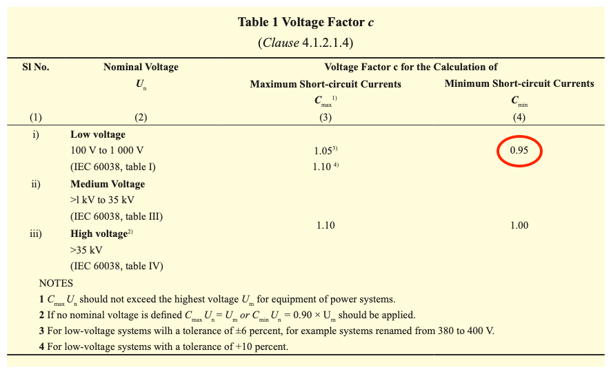
Hence:
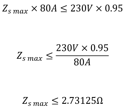
This Zs max is the maximum permissible earth fault loop impedance of the circuit.
In order to ensure that this maximum permissible earth-fault loop impedance value is not exceeded, the earth-fault loop impedance at the extremity of every circuit needs to be calculated and shall be below Zs max.

4. Calculation of Earth fault Loop Impedance
Consider a single-phase final circuit, where the earth-fault loop impedance at the source is 0.35 Ω, with the circuit run in 2.5mm2 Cu, Class 2 conductors. The circuit is being protected by a B16, MCB to IS/IEC 60898-1.
The calculation of earth-fault loop impedance at the extremity would be as follows:
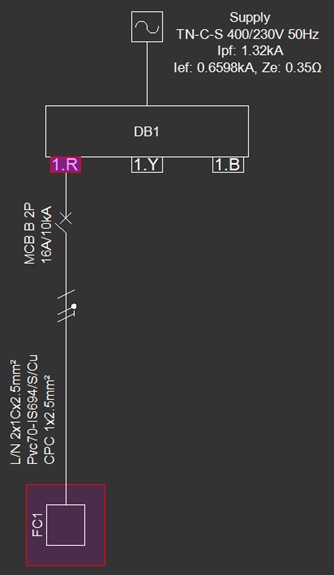
where

Zsource is the impedance the source
z1 is the impedance of the 2.5 mm2 line conductor.
z2 is the impedance of the 2.5 mm2 PE conductor.
The impedance of the source is known:

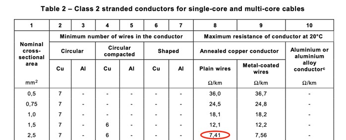

Note: the 1.2 factor is calculated from Annex A, IEC 60228:2004 to account for an increase in conductor resistance (70C operating) from when the measurement of conductor resistance takes place (20C ambient).

Hence, it is ascertained that for the final circuit under consideration, the earth-fault loop impedance at the extremity is 0.61676 Ω, which is less than the maximum permissible value of 2.73125 Ω. Therefore, protection against electric shock can rely on the protective device’s automatic operation.
5. Problems associated with manual calculations
In an actual installation, this calculation will be more complex and is required for:
- Every outgoing circuit of a panel or distribution board
- All final circuits (sockets, machinery or other loads)
- Repeated for every circuit for each source (Transform or DG)
- MCCBs, ACBs or Relays based on their adjustable operating characteristics
- Circuits where more than one parallel PE conductor exists (e.g. armour and separate PE conductor)
Due to the above, performing such a calculation manually or through the use of a spreadsheet has a high probability of manual error, which is unacceptable as it can compromise human safety.
6. Earth Fault Loop Impedance calculation using Electrical OM NEC-IN
The software can complete a similar calculation in a few simple steps:
1. In the schematic tab, a 3-phase 400/230V source is inserted and the source earth fault loop impedance is set to 0.35 Ω:
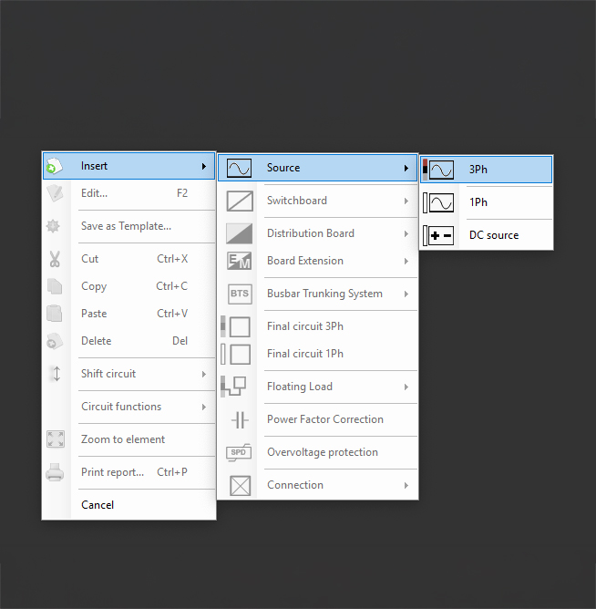
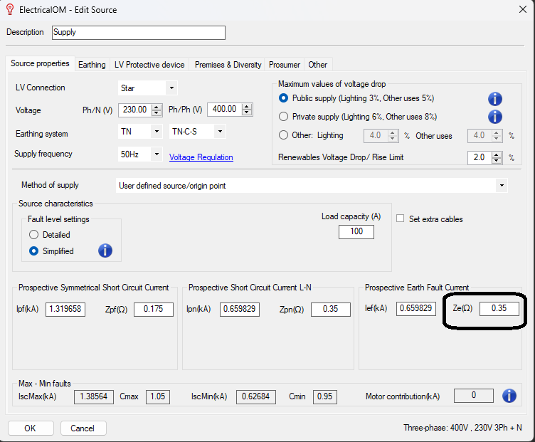
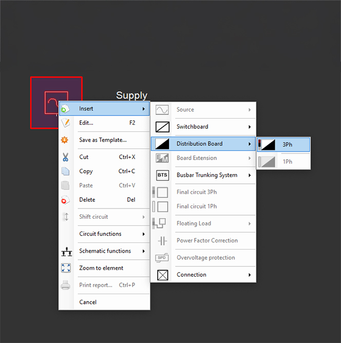
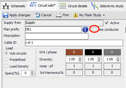
2. A three-phase distribution board is supplied from the source and in the circuit edit tab, changes made to this distribution circuit. Since in the case of the example, only a final circuit is being considered, the “use conductor” checkbox is un-ticked as we are not considering the impedance of any circuits supplying the final circuit:
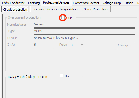
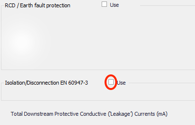
3. Since in the case of the example, only a final circuit is being considered, from the circuit edit tab, the “use” checkbox is un-ticked for the overcurrent protective device as well as the isolator:
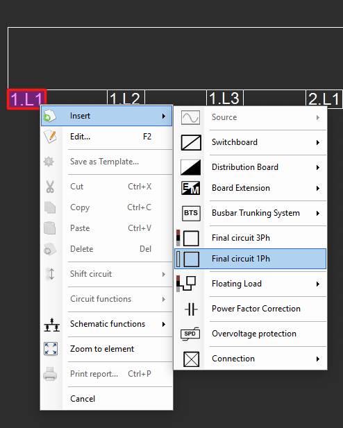
4. In the schematic tab, the final circuit being considered is now added to the distribution board and IS standards is selected for the conductors:
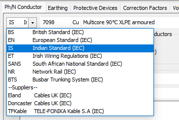
5. In the circuit edit tab, in the Ph/N conductor section, the IS standard selected is IS 694, copper conductor with cross-section area of 2.5mm2 with 15 meters length:

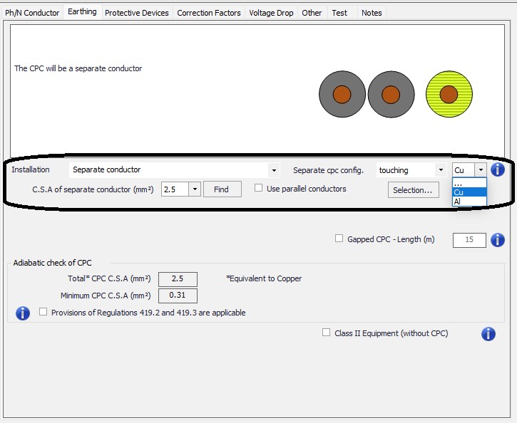
6. In the circuit edit tab, in the Earthing section, the cross-sectional area of the protective conductors is set to 2.5 mm2 and the conductor is copper:
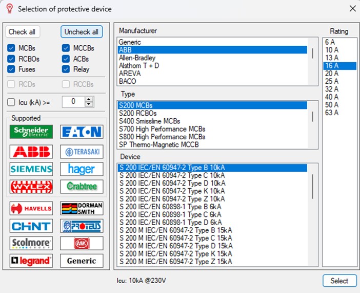
7. In the circuit edit tab, in the protective devices section, the protective device is selected to be a 60898 Type B, 16A MCB:
8. The final circuit has now been modelled. In the circuit edit tab, the values of Ze (external), Z1+Z2 and Zs are automatically calculated:
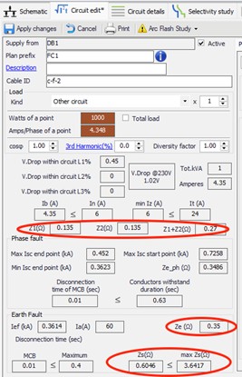
The value of earth-fault loop impedance at the circuit extremity (Zs) is also compared to the max Zs for the selected protective device, which has automatically been calculated.
As observed by simply entering the details of a circuit into ElectricalOM NEC-IN, the software automatically performs a calculation for the earth-fault loop impedance of a circuit. Furthermore, it compares this with the calculated maximum permitted earth-fault loop impedance for the selected protective device as required by IS 732:2019 and SP 30:2023, saving electrical designers hours of time on large projects.
A reference report for a large commercial office project generated directly from EOM NEC-IN is attached for reference (in PDF). Report Export for EFLI.
A EOM NEC-IN can handle more than 500+ distribution boards (DB’s or panels) and 5000+ final circuits seamlessly.
The Software can also do all the calculation required by a Electrical Designer (Consultants) as per National Electrical Code of India (SP 30) with 100% accuracy and 50% saved time.
For free demo and trail version of the software please fill the forum in the link: https://tgelectro.com/contact.php
or
You can also contact us at
Email Id: info@tgelectro.com
Phone: +918925584800
